RPM882-H14
Photo Link Module
3/9
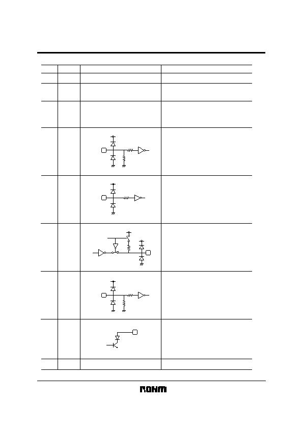
Terminal description
Terminal
Circuit
Function
Pin No
2
1
VIO
GND
Supply voltage for I/O pins.
(TX-RC, PWDOWN, RXD, TXD)
Ground
Power Supply Terminal
For preventing from infection, connect
a capacitor between VCC (3pin) and
GND (1pin).
Connect to Ground.
3
VCC
PWDOWN /
LED Mode
RXD
TXD
LEDA
Shield Case
4
5
6
7
8
TX-RC
VIO
VIO
200k
LED
VIO
200k
VIO
VIO
300k
PWDOWN
RC Transmitting Data Input Terminal
H : LED Emitting
CMOS Logic Level Input
Holding TX-RC='H' status, LED will be
turn off approximately 48祍.
Power-down Control and LED
Intensity switching Terminal
CMOS Logic Level Input
When input is 'H', it will stop the receiving
circuit and Pin-PD current.
H : POWERDOWN (RC transmitting Mode)
L : OPERATION
Receiving Data Output Terminal
CMOS Logic Level Output
When PWDOWN (5pin)= 'H', the RXD
output will be pulled up to VIO at
approximately 300k&.
Transmitting Data Input Terminal
IrDA TXD input at PWDOWN=L
(Remote control transmitting input at PWDOWN=H).
H : LED Emitting
CMOS Logic Level Input
Holding TXD="H" status, LED will be
turn off approximately 48祍.
LED ANODE Terminal
Other power source can be used
difference between LEDVCC and VCC.
LED current depends on LED load
resistance value at RC mode.
发布紧急采购,3分钟左右您将得到回复。
相关PDF资料
RPM960-H14E3A
MODULE IRDA 1152KBPS 8SMD
RPM971-H14E3A
MODULE IRDA 5MBPS 8SMD
RPM972-H14E3A
MODULE IRDA 4MBPS 3V SMD
RPM973-H11E2A
MODULE IRDA 4MBPS FIR COMPATBL S
RPM973-H16E4A
MODULE IRDA 4MBPS FIR COMPATBL S
S0106H0012XHAGNX420
RESOLVER 1" HOUSED W/TRANSFORMER
S0106H0012XHAGNY420
RESOLVER 1" HOUSED W/TRANSFORMER
SA.PANEL.20
ANT 17DBI BASE STATION W/N
相关代理商/技术参数
RPM882-H14E2A
功能描述:光纤发射器、接收器、收发器 IRDA IR COMM SIDE VIEW W/SHIELD RoHS:否 制造商:Omron Electronics 产品:Transmitters 数据速率:3.5 Gbps 波长:850 nm 最大工作温度: 最小工作温度: 封装 / 箱体: 封装:
RPM882-H7
制造商:ROHM 制造商全称:Rohm 功能描述:IrDA Infrared Communication Module
RPM882-H7E2
制造商:ROHM Semiconductor 功能描述:IRDA COMMUNICATION MODULE SIR - Tape and Reel 制造商:ROHM Semiconductor 功能描述:IC IRDA IR COMMUNICATION MODULE 制造商:ROHM Semiconductor 功能描述:IRDA COMM MOD SIR
RPM90
功能描述:测试引线 IND. TRIGGER PICK
RoHS:否 制造商:Pomona Electronics 设备类型:Patch Cords 连接器类型:Banana plug (stackable) on both ends 长度:60 in 颜色:Black
RPM922-H11
制造商:ROHM 制造商全称:Rohm 功能描述:IrDA Infrared Communication Module
RPM922-H11E2A
功能描述:光纤发射器、接收器、收发器 IRDA TXRX 0.1152MBPS 3V 7PIN RoHS:否 制造商:Omron Electronics 产品:Transmitters 数据速率:3.5 Gbps 波长:850 nm 最大工作温度: 最小工作温度: 封装 / 箱体: 封装:
RPM960-H14
制造商:ROHM 制造商全称:Rohm 功能描述:IrDA Infrared Communication Module
RPM960-H14_05
制造商:ROHM 制造商全称:Rohm 功能描述:IrDA Infrared Communication Module
